How to Install: Linus® Smart Lock on your Yale Linus® Adjustable Cylinder
How to Install the Linus® Smart Lock on an Adjustable Cylinder
Please note:
- Linus® Smart Lock is designed to be mounted on the inside face of entrance doors.
- If you have a Cog cylinder the Linus Adjustable cylinder will not work in your door. We recommend you purchase a Cog cylinder with an emergency function for DIY installation or contact your local locksmith.
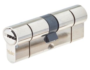
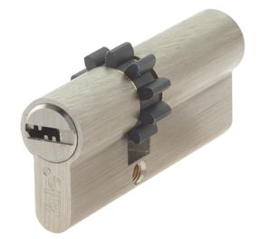
What is a Cog Cylinder?
A cog cylinder also has the euro profile shape like the standard cylinder, the difference is that it has a cog cam and not a standard euro cam. The cam is the part that rotates in the middle of the cylinder. Below you will see cog cylinder on the right

Step-by-step installation guide
Step 1: Measure
Before we start, please measure how far your existing cylinder sticks out from your internal door furniture.

If it is less than 3mm, please keep this in mind for later in the installation process.

Step 2: Remove the existing cylinder
Unscrew the existing cylinder fixing screw below the bolt on the lock.

You will then need to insert and wiggle the key about 15 degrees to allow you to pull the cylinder from the door.

Step 3: Measure existing cylinder
Measure the size of your existing cylinder by measuring the length of each half, to the centre of the cam. Make a note of both the internal and external measurements so you can adjust the Adjustable cylinder correctly.

If during Step 1, your cylinder protrudes from the internal side of the door by less than 3mm, you now need to add an additional 3mm to your internal measurement. This ensures that the Linus® Smart Lock can be easily attached.
If your measurements are 30mm on the external length and 30mm on the internal length you don’t need to do anything as the Adjustable cylinder can be fitted as is. Please skip to Step 11.

Step 4: Adjust cylinder length
Make the Linus® Adjustable cylinder the same length as your current cylinder, which in this example is 60/40mm.
60mm on the external part and 40mm on the internal (including the 3mm mentioned in Step 1).
Use the appropriate external and internal spacers to achieve the same length.

Step 5: Select spacers and faceplate
Pick the external spacers and then the external faceplate that you require.
If the external length of your existing cylinder is between 35mm and 45mm, please use the shorter faceplate.
If it is between 50mm and 60mm, please use the longer faceplate.
Step 6: Loosen screws
Using the small Allen key, loosen the screws at the bottom of the cylinder until both filler pieces can be removed.

Step 7: Assemble external spacers with external faceplate
Assemble the external spacers with the external faceplate onto the Adjustable cylinder, making sure that the smallest external spacer is closest to the cylinder.
Secure in place with the screws at the bottom of the cylinder.

Step 8: Test that key turns
Once you have assembled the external spacers and faceplate, insert the key in the external side of the Adjustable cylinder and make sure it can turn the Adjustable cylinder freely.

Step 9: Add internal spacers
If the internal measurement of your existing cylinder is more than 30mm (including the 3mm mentioned in Step 3), add the internal spacers together to form the difference between 30mm and the cylinder’s internal length.
For example, if your current cylinder has an internal length of 40mm, use the 10mm internal spacer. If your cylinder length was in-between two spacer sizes, use the longer size.
Step 10: Assemble internal side
Next, assemble the internal side of your Adjustable cylinder using the correct spacers for your door (sizes are printed on the side of the spacer), securing them in place with either the short screw or the longer screw in the central hole with the larger Allen key.
The smallest spacer should be closest to the Adjustable cylinder.

Step 11: Tail-bar
After you have fully assembled your Adjustable cylinder, insert the tail-bar into the Adjustable cylinder. If your internal measurement was equal or less than 45mm, use the shorter tail-bar that was provided, if not, use the larger one.
Then make sure you can turn the Adjustable cylinder freely using the tail-bar.

Step 12: Finish cylinder installation and mount Linus®
Turn the tail-bar on the internal side of your door so that the cam lines up with the body of the Adjustable cylinder and fits in the hole in your door. You may need to wiggle the tail-bar to get it in place.

You may also need to loosen your current door furniture (rose/handles) if it’s tight around the Adjustable cylinder.

Secure the Adjustable cylinder in place with the cylinder fixing screw, and re-tighten the door furniture. Add the mounting plate onto the internal side of the Adjustable cylinder making sure that you have 3mm extended in order to fix the mounting plate.
You may need to loosen the grub screws (the screws on the mounting plate that go around the cylinder) in order to secure the plate properly. This can be done using the Allen key that is provided in the box.
Fix the plate in place with the two small screws.

Add the tail-bar to the internal side of the Adjustable cylinder, ensuring it can turn the Adjustable cylinder freely. If the internal measurement is 45mm or less, use the short tail-bar. If it is above, use the long tail-bar.

The next step is to mount your Linus® onto the fixing plate pushing the top of the unit onto the mounting plate first." "Close the ‘wings’ on the Linus® unit to securely fix it in place."
